
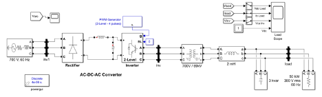
This model was developed to understand how our Hydroelectric stream divers would connect to the grid. This model gives our team a better understanding of how an interconnect would look using a 3-phase PMSG source for power injection to the local grid transmission line. There is also a need we learned from interviews with Voith representatives that while stream-divers can connect directly to the grid under constant flow and head conditions, Frankfort Kentucky does not provide us with said conditions as discussed in the flow analysis section of this report. Therefore, the inclusion of such a modeled power converter provides our design with an understanding of the need to produce higher efficiency within our system. The model build itself presents the viewer with:
- 700 V, 60 Hz 3-phase source modeled to produce an input like that expected from the stream divers PMSG output signal.
- Universal bridge–diode power electronic devices provide the AC to DC conversion required for frequency, phase, and amplitude manipulation for harmonic filtering and grid interconnection.
- LC series filter: for further harmonic filtering before further power conversion
- Two-level three-phase converter with IGBT/diode switching devices for DC to AC power conversion.
- Transformer 700/69kV step-up modeling the requirements of our designs nearby local (FPB-utility) 69 kV transmission line for transmission to the nearest substation.
- 50 kW sink to produce a load upon the simulated power conversion, resembling what a nearby local Frankfort load would produce.
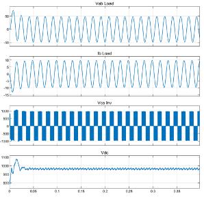
The figure above is 4 different output stages through the two-stage conversion process. The top two signals represent the 60 Hz current and voltage inputs to our 50 kW power load. The third signal is the effect of the inverter and pulse width modulation conversion technique for DC/AC conversion before the transformer step-up. The last graph shows the rectifier conversion of the PMSG 3-phase AC output to a DC signal for power conditioning and filtering. On this last signal, a large jump can be seen as the 3-phase generator is brought up to speed as fast as possible in the ideal simulation, this leads to a large overshoot that could be corrected with proper control implementation or Maximum power point tracking (MPPT).